Been a while I didn’t write here, again you might say… But there’s a reason behind that. Remember that Velux hack for Snips? Project Alice – Raspberry voice controlled Velux
If I remember well, the first comment I got on Discord was “It’s not professional at all”… Well, that’s not wrong, but it is working you know. But still, I decided to take it to the next level. Before the whole story, let’s talk milestones:
- Designing electrical schematics DONE
- Designing PCB DONE
- Printing, etching PCB DONE
- Mounting PCB DONE
- Connecting to Velux remote and Raspberry pi zero DONE
- Changing python script and have everything working as before DONE
- Making a tutorial
- Making a video
- Making pictures
- Making a full functional Snips package
- Distributing as open source
- Proposing my services for the PCB against a small payment without being a commercial entity in the eyes of Snips 🙂
And let’s clarify this: I’m not an electrician, I’m a precision mechanic. I did a little electronic at school, a bit more by myself, but never did this much. Oh and yes, special credits to my friend mpbs that supported and guided me for the electrical part.
So, when you first think about chips, well, England comes first if you’re british, for other you think thin sliced potatoes fried with salt orr whatever. I had never thought about using a chip even less about etching my own PCB. I was working using relays and prototyping board. Lego VS Duplo? But well, I love to learn, I need to try and create so I went in. Google…. Or whatever engine… Try to find information, you’ll get everything and nothing about creating your own PCBs… You can print them with a CNC, you can use a UV light, an iron, a laminator, hammer, whatever. Products? You can use ammonium, sodium, ferrite. No good leads to what, when, where. How do you finish your board? You can use Sur-Tin, you can use a special varnish and others. I won’t describe everything I bought… To find the way that worked for me.
Ok, first part was buying some PCB. I chose epoxy with 0.35mu copper, photo resistant applied, like this, by Scankemi. I also bought a UV tube by Philips and a few part to mount it.
Then, I thought about designing, so I googled for a good PCB design software. Many choices, but I ended up using EasyEda, because I thought that if by any chance I couldn’t make my own board I could always just order it from them directly. It’s a nice cloud software, does the job, auto router is handy but you’ll need to make the final corrections yourself. I recommend it!
After a couple of tries, I ended up with my schematics, on one-sided board. Printed, about 5 times until the orientation was correct and I tried the uv light! Well, placed the pcb with the transparent paper on top of it encased in a photo frame to make sure it’s really pressed together. Tried 30 secs, a minute, 2 minutes etc… Nothing. After bathing the pcb in the photo resistant remover, everything was gone and I ended up with a nice copper piece…
So, I decided to try a toner transfer. Back to printing, on 110g/m2 glossy photo paper. The glossy part is important, you won’t have a nice transfer otherwise. You need to mirror the copper side!! Back to online search, I decided to try my wife’s toy, the iron! With more or less success I should say, the transfer is everything but optimal… After trying again and again both methods I decided the quality wasn’t what I was expecting. So I ended up digging in my office, at work, to find an old laminator, the Grail! Why? Because those old ones aren’t automated in temperature and speed! Ok, cutting the paper, placing it on the pcb, tape it nicely and off in the laminator @ 160°C. I found out that going through about 22 times, at lowest speed possible and reverting the pcb every time to make it heat all the way gives the best results for me. I usually go until I can’t touch the pcb anymore. Directly after, you just throw it under water and let it soak until the paper gets totally transparent. Slowly peeling the paper off and the tracks were nicely transferred!! So happy!
Next step, was etching… What solution to use? Ammonium, sodium, ferrite? Well, decided to go for Ammonium chloride just because… It’s the only one I could find in Switzerland. Of course, don’t bother reading about it and try it cold, it will just take 10 times longer. Seriously, wear gloves, do the mix with hot water, 65°C works well, and put the pcb in and keep moving it slowly with a plastic pincette or wooden sticks. Don’t use metal! After a while, the entire copper will be eaten away and your ammonium will have turned blue. Taking the pcb out, rinsing under running water and wow! The first etching seemed perfect! Oh yeah, pour the liquid in a plastic bottle and store it for further use. Store it away, correctly marked. Now, the toner was still on the pcb… Ok, found out that Aceton is perfect and immediately removes the toner. You end up with a nicely designed track!


Next step was making holes and soldering the components on it… Easy!


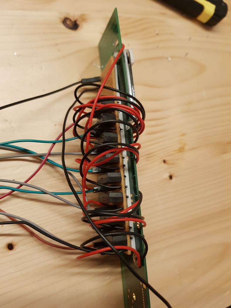
Only to find out that it’s a cable mess, it’s not nice and it doesn’t work. Not enough current to power the remote when going through the TI4066 chip. Back to drawing board, both on EasyEda and in my head. Decided to go full power, two-sided pcb, Mosfet, resistors etc etc. Again, used the laminator technic for toner transfer, but on both side of a double-sided pcb! Took some time to make sure the papers were correctly aligned but I ended up being good at it. Because yes, I made about 6 pcbs before the final working one… The next problem was, hey, two sided, but how do you connect side A to side B? Well, bought some silver copper wire and just soldered it on both side of the connecting hole. Of course, the army of wires from the controller to the board had to go, sorry. So I decided to use the very same silver copper wire to solder on the controller buttons and then directly on the board. The board becomes a hat for the remote controller, non removable once the buttons are soldered. But also a hat for the raspi zero! No more wires, expect for the remote power!


Oh, almost forgot! Actually, I found out when doing the last pcb… You need to protect the tracks or you’ll end up with a rusty copper board. For that you need some chems again. And it’s not easy to get it in Switzerland, because it’s extremely acid. I’ve used Sur Tin. You prepare the mix, soak your board for about 2 minutes in and it’s done. But you wear long clothes, gloves, glasses. That stuff ate my floor! And finally, the board is done! A few corrections to it, such as the MOSFET being 2mm too low and the power connector too, but that’s for the next ones I’ll do. Ok, enough talk, a few pictures of the finished product


Want to know what I used? Here a few links! And dev safe!

Thanks for documenting your work! It has inspired me to hack my klr100. I have a few questions… if i simply want to open or close a group of 2 windows then I only need two reed relay switches? Do I really need to reboot the klr100 everytime?
I will be using an esp8266 which has 3.3V logic pins. I will be sending mqtt commands to it over wifi to either trigger a high (3.3v) or low (0v) so i presume this will work for simple open /close control?
cheers
Stuart
LikeLike
Hi! Great if it motivated you!
About the reboot… I really encourage you to do it. Because most likely you have rain sensors on your windows. All the actions are triggered from home screen, but if you try to open and the rain sensors are stil lwet per exemple, the remote control will show a warning screen instead of going back to home screen. Or if it can’t reach a product. Or any other problem. Which means, whenever you try another action, the commands will execute from that screen and will lead to an error, or worst, a mess on you remote as it happened quite often for me. I really encourage you to do the reboot, it’s 15 seconds that will save you hours and hours of reprograming your remote and costs not much
About the reed relays, I’d say…. don’t go that way anymore, experience made, the mosfets are much more reliable. Making the pcb, if you’re not ok with it, is not expensive if you order them at JLCPCB, first order is…. 2 usd…. The components on the pcb itself cost let’s say about 10 bucks max
If you want to control 1 or 100 products, you will always need:
– Select button
– Ok button
– Up button
– Down button
– Up arrow button
– Down arrow button
So 6 reed relays anyway. This is only true if you want to be able to be able to control different products depending on the situation. If you are scared of doing the pcb and soldering the components, I can do it against a little payment
LikeLike
Btw, if you want an easier hack because you want to trigger always the same products, hacking a KLI 310 is a good idea also. The idea is the same, you have only 3 buttons and no reboot needed 🙂
LikeLike